EEE333 Hardware Design Language and Verilog
Overview of HDL
Hardware Description/Design Language
HDL’s were made out of necessity once chips became too complex. Gordon Bell and Allen Newell introduced the concepts of Register Transfer Level Representation (RTL).
System Verilog is the modern implementation of Verilog; largely, academia is moving to Verilog, along with many companies.
- Verilog is derived from C programming language
- Weakly typed language, predefined datatypes
- No dynamic memory allocation
- Comparatively flexible
- Ambiguous simulation semantics
- Very important to follow guidelines to avoid trouble
- Debugging easier, simulation control supported
- Developing rapidly with new features
- VHDL is derived from Ada
- Verbose self documenting style
- Strongly typed, converted explicitly
- Dynamic memory allocation with pointers
- Unambiguous and clear
- Portable
- Debugging harder, simulation control not supported
Structure of the Language
Verilog is “more like a spice netlist”. The spice netlist describes how components are connected at nodes. Then it describes how certain nodes are driven.
A connection in a netlist is always made and can be described by the continuous assignment statement.
assign A = B; *//permanently drives net B with the value of net A
Verilog Module Organization*
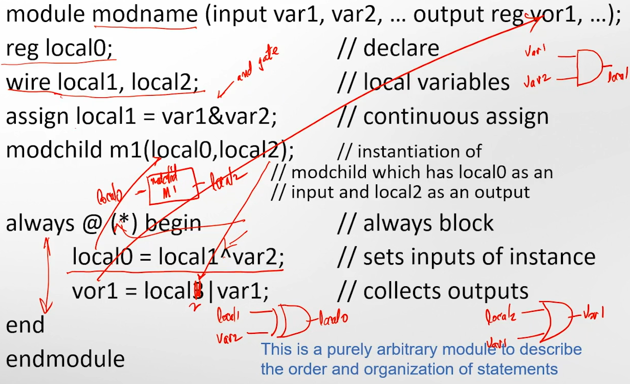
module modname (input var1, var2, ... output reg vor1, ...);
reg local0;                  // declare
wire local1, local2;         // local variables
assign local1 = var1&var2;   // continuous assign
modchild m1(local0,local2);  // instantiation of
                             // modchild which has local0 as an
                             // input and local2 as an output

always @ (*) begin           // always block (†)
  local0 = local1^var2;      // sets inputs of instance
  vor1 = local3|var1;        // collects outputs
end
endmodule
*This is a purely arbitrary module to describe the order and organization of statements
† local0 “drives the input” of modchild module m1.
The always block “collects inputs of an instance and sends them to a module” in this case.
More details
A module describes a component; it has input and output nodes.
The relationship between input and output nodes is describes within the module.
This module can be instantiated in a design (netlist) like a component.
You can then instantiate the same type of component any number of time sby instantiating the module with a different name.
Scope
Variable scope it local. The only way modules can see information within one another, is using the port list containing inputs and outputs. Verilog is a low level language that doesn’t do self-typing or declaring for you, so all variables must be declared in each module by the programmer.
Conditional Behavior
Imagine we want Y=~X when Z=0, but Y=1 when Z=1:
module testidea(input X, input Z, output Y);
assign Y=(Z==0)?~X:1; //this is called a ternary
More generally: assign Y=(condition)? value of Y if condition true : value of Y if condition false
Note that in this setup, Y must be declared as a wire.**
We can also use always to accomplish this:
module ...
reg Y;
always @ (X,Z)
    if(Z==0)
      Y=1;
    else
      Y=0;
This does the same thing; always is always running but what is inside the always only runs if the sensitivity list, X or Z change value or level. Stated alternatively: the always runs if Z or Z change.
That means Y has to be defined to hold the value between these changes which is called a software register, so Y must be delared a reg.
That is, Y must be data type reg.**
**Though, in later System Verilog this can be declared logic.
The register is a 1-bit declaration in this case, which means that the formatting should actually be
...
Y = 1'b1;
...
Y = 0'b1;
...
Clock Signal
In most circuits there is a synchronizing clock signal, which we can call clk.
To synchronize signals with the clk we can use always but we synchronize on the edge of a clock signal, not the level.
reg [7:0] cnt; //declares 8-bit var count
always @ (posedge clk, posedge reset) //runs when either positive edge is detected
    if (reset)
      cnt <= 8'b0; //resets cnt to 8-bit -; non-blocking
    else
      cnt <= cnt + 8'b1; //adds 8-bit 1 to 8-bit cnt; non-blocking
NOTE: the inequality symbols above are actually <= – formatting shortcuts take over on code blocks.
Blocking vs. Non-Blocking Assigns
This code is synchronous, it uses a non-blocking assign (<=).
Non-blocking assigns are done in a very different way.
Here’s an example of a blocking assign:
// assume initially outA
always @ (*) begin
  outA = xval;
  outB = outA;
end
outB will be xval.
Conversely, non-blocking assigns are not determined one-line-at-a-time, but the left hand side is assigned to the right hand side at the same time. An example:
// assume outC = 1'b0;
always @ (posedge clk) begin
  outC <= xval;
  outD <= outC;
end
NOTE: outD will be 1’b0 ! Not xval. This is because everything on the right sides of the assignment (<=) was evaluated first. This can be used for something called pipelining.
Some Rules
- Within a module, a variable can be assigned in only one always, assign or module instance, otherwise it is like connecting outputs of gates — zap, and the compiler won’t do it
- variables cannot be doubly driven
- continuous assign (using the assign keyword) cannot be inside an always, because they do different things
- assign drives a value continuously
- always assigns it a value under certain circumstances then holds it
- Variables assigned a value within an always must be declared reg in Verilog (rule changes slightly for System Verilog)
- Variables assigned a value in a continuous assign statement must be declared wire and use the keyword assign
- In System Verilog the logic datatype can be used for either reg or wire, whichever is needed, resulting in less errors
- These are important rules, and you will see them again
Introduction to Verilog
Verilog and other HDL’s actually eliminate the need for Boolean minimization. Designers using HDL write a text-based description of the circuit, compile that description to verify its syntax, and then simulate the circuit to verify its functionality. Designers might then use an FPGA to simulate the actual function.
Generally, a Hardware Design Language is a “software that describes hardware”. Designers must keep the hardware in mind when writing the HDL. Remember, we want hardware to be small and fast.
Verilog was initially designed in the 80’s, acquired by another company who made it public in 1990. IEEE standardized it in 1995 and it became regulated by Open Verilog International (OVI).
Verilog Abstraction
There are various levels of abstraction in Verilog, encapsulated in models:
- Structural Model: logic is decribed at the register and gate level
- Behavioral Model: simple behavior is modeled–this is the highest level of abstraction
- Register Transfer Level: typically written by the synthesizing software
Structural Models of Combinatorial Logic
- Encap’s a description of its functionality as a structural or behavioral view of its input/output relationship
- Can/should be partitioned into major functional blocks
- The objective of the gate level netlist is to describe the function, not how to acheive it. Actual implementation is left to the synthesizer and it much different
Remember that a module is a routine that describes a portion of a design:
module AND2(output out1, input in1, in2);
  and(out1, in1, in2);***
endmodule
***Notice that this executes the functionality of an AND gate. That’s what makes this a structural model.
This particular example is a little contrived since we already have an AND gate primitive.
In the structural mode, the schematics/gates can be described directly as a netlist of gates. Logic is described at the register and gate level. So the example above is a structural model of a 2-input AND gate. It doesn’t describe the implementation of the function.
Primitives
The user can define their own primitives using a table description. The only limitation is that these primitives can only have 1 output.
The builtin primitives are predictable: and, nand, or, nor, xor, xnor.
Procedural Algorithms
We can describe a function using Boolean equations or procedural algorithms as well. We use the assign statement to do this.
So to summarize the last few sections: Structural Model:
module AND2(output out1, input in1, in2);
and (out1, in1, in2);
endmodule
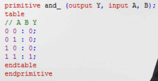
Primitives:
primitive AND2(output out1, input in1, in2);
table
0 0: 0;
0 1: 0;
1 0: 0;
1 1: 1;
endtable
endprimitive
Data Flow Modeling/Boolean Equation based Models:
module AND2(output out2, input in1, in2);
assign out2= in1 & in2;
endmodule
Procedural Modeling:
module AND2(output out3, input in1, in2);
assign out3= (in1==in2) ? in1 : 1'b0;
endmodule
Language Specification and Behavior Models
Comments
Verilog supports the typical C-style comments:
// begins a line comment
/*
Muliple lines; "little more dangerous"
*/
Variable Name Rules
- Cannot start with a ‘$’, but it can have one in it.
- No spaces.
- Case sensitive.
- Can contain underscores, letters, and numbers.
Internal variables are defined as a wire, typically connecting two nodes. Note that this is the default, so the statements can be omitted. Think of wires as a connection between to logic gates on a typical logic diagram.
A wire is a type of “net”. It must be continuously driven, it does not “store” a value. Wires need to be declared before being used.
- inputs to a module are always considered wires
- outputs of a module can be wires or something else
- wires can be single bit or multi-bit (e.g. 8-bit, 16-bit, etc.); these are called vectors, which are also called buses.
Reg: usually represents latches, flip-flops, or memory. Stores a value and it sued in procedural assignments (inside procedural blocks).
int: Used in test benches. 32 bits in width.
Vectors and Arrays
Nets and Regs can also be defined as vectors. That declaration look like this:
wire [7:0] bus; //8-bit bus
Or, the declaration can be made as an array (like a matrix):
wire [3:0] ids [2:0]; //array of 3 ids, each having 4 bits
// ids[0], ids[1], ids[2], etc.
Reminder about MSB’s and LSB’s
The highest bit is the most significant bit (MSB) and the lowest bit is the least significant bit (LSB). In a vector SUM[3:0], the MSB is SUM[3] and the LSB is SUM[0].
Signal Values
Verilog supports 4 values: 0, 1, x, Z. X is an unknown logic value, and Z in a high impedance state or “floating”. A line will have a value of X if it is not being driven by anything.
Verilog numbers are specified as size'basevalue number.
- Binary (
'b):4'b1010(4-bit binary 1010) - Hexadecimal (
'h):8'hFF(8-bit hex FF) - Decimal (
'd):16'd255(16-bit decimal 255)
Size can be omitted (e.g., 'b101), defaulting to 32 bits, and x or z can represent unknown or high-impedance values.
Bitwise Operators
Bitwise Operators
| Operator | Description |
|---|---|
& |
Bitwise AND |
| |
Bitwise OR |
^ |
Bitwise XOR |
~ |
Bitwise NOT |
~^ |
Bitwise XNOR |
These are performed at the bitwise level.
Logical Operators
Bitwise Operators
| Operator | Description |
|---|---|
! |
Logical NOT |
|| |
Logical AND |
&& |
Bitwise OR |
Per usual, if compared values are non-zero, they are considered true.
Arithmetic Operators
The usual/expected arithmetic operators are available: *, /, %, +, -.
Procedural Algorithms (Behavioral Models)
| Symbol | Description |
|---|---|
< |
less than |
<= |
less than or equal |
> |
Greater than |
>= |
Greater than or equal |
== |
equal to |
=== |
equal to (includes z and x) |
!= |
not equal to |
!== |
not equal to (includes z and x) |
module AND2 (output out1, out2, out3, input in1, in2);
and (out1, in1, in2);                   //structural model
assign out2= in1 && in2;                //Boolean expression
assign out3= (in1 == in2) ? in1 : 1'b0; //procedural model
endmodule
Procedural blocks will give us even better programming capabilities.
| Initial Block | Always Block |
|---|---|
| Starts at time 0 | Starts at time 0 |
| Can contain any number of statements | Single statement, or multiple statements nested between a begin and end block. |
| There can be multiple initial blocks per module | Always blocks can run again after ending, if the trigger event occurs.‡ |
| Must drive reg variables | Must drive reg variables |
| No continuous assign statements (wouldn’t make sense since initial blocks specify when variables are assigned values) | Will not have assign statements. |
‡The contents within the always are called “sensitivity lists;” the list of events that will trigger the always block.
Variables on the left hand side of the assignment must be deflared as reg (can be defined as logic in system verilog).
Begin and end blocks: just what they sound like. They are used with always, if/else loops, etc.
always @ (posedge clk) begin
  ...
end
//optionally, you can use a colon to label your begin statements:
begin: label here
  ...
end
Additional Always Blocks
There are 3 additional types of always blocks designed to reduce common errors.
always_ff is for describing flip-flop behavior. Only reevaluates if the sensitivity list changes, like usual.
always_latch is for describing latch behavior. Reevaluates if clk or d changes. Equivalent to always @ (clk, d).
always_comb takes the place of always @ (*). It executes at time 0, unlike a typical always block.